A (Very) Brief Explanation of LLVM
Posted on Sat 09 November 2024 in high_level_synthesis
The purpose of this post is to describe the bare minimum preliminary background that's required to understand subsequent posts. If you already know about dataflow and control flow graphs, you can happily skip this post. Otherwise, read on!
The Dataflow Graph (DFG)
A dataflow graph (DFG) is a directed acyclic graph (DAG), \(G(V,E)\), where each vertex \(v\in V\) denotes an operation. The operation is taken from some discrete set of operations that we permit our DFG to leverage. The simplest set of operations we could envisage might be a set of arithmetic operations, i.e. addition, multiplication, etc., but we could also include basic computational operations like loads and stores. For the moment, we needn't complicate this picture further, but it's worth keeping in mind that each operation, \(o_k\) has an associated latency, \(\ell(o_k)\). Without delving into the underlying hardware, the latency of an addition, for instance, is generally speaking less than the latency of a multiplication.
An edge in the DFG is a directed link between two vertices, so that \(e_{ij}\in V\) is an edge originating at vertex \(v_i\) and terminating at vertex \(v_j\). An edge indicates that the output from the origin vertex's operation constitutes an input to the destination vertex's operation. The operation associated with the vertex \(v_k\) can only be completed once all of its predecessor vertices have completed their respective operations. Similarly, none of the successor vertices to the operation which is undertaken at vertex \(v_k\) can be completed until \(v_k\) is complete. The sets of predecessors and successors to a vertex, \(v_k\), are useful quantities for which to provide a nomenclature; to this end, we use \(\mathrm{pred}(v_k)\) and \(\mathrm{succ}(v_k)\), respectively.
Let's take a trivial example. The expression \(x = a + b\times c\) can be formulated as a DFG; the multiplication operation takes \(b\) and \(c\) as inputs, and ouputs a result which, along with \(a\), forms an input to an addition operation, the output of which is \(x\).
It's potentially illustrative to consider a genuine mathematical problem we may want to subject to this type of analysis. The simple harmonic oscillator is defined by the second-rder differential equation:
Splitting this into two coupled first-order differential equations:
Then, using the Euler method, we can deduce the means by which we can numerically solve the harmonic oscillator:
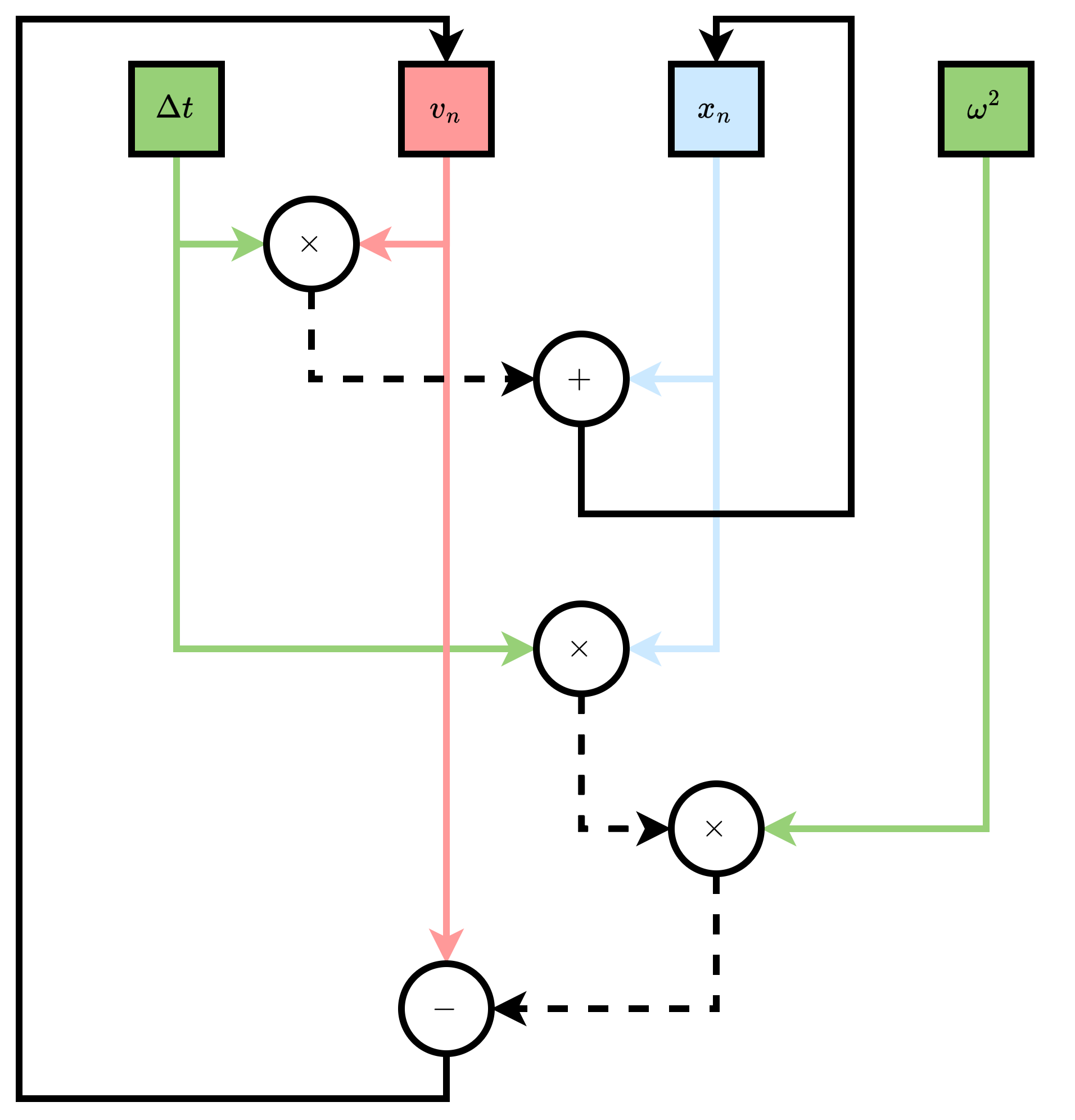
We can draw a single iteration of this out graphically as a DFG. We've provided backedges to update the values \(x_{n+1}\) and \(v_{n+1}\), but recall that a DFG is a DAG, and so these backedges technically render the above ill-formed as a DFG, hence the necessity to specify that we can only draw out a single iteration of this as a DFG. We'll consider this a little more in the following section.

r
The Control Flow Graph (CFG)
It's tempting to think that the DFG provides all we need to analyse an algorithm. However, as we noticed, some algorithms require backedges to encode updates of values and iteration, fairly critical components to the vast majority of algorithms. Furthermore, branching logic (if-then-else) is a core component of most algorithms
, but this can't be represented in a DFG. The control flow graph (CFG) provides a mechanism to capture these intricacies.
It's perhaps useful to think of a CFG as a FSM, where each state comprises a DFG. Consider the (hideously simplified) leaky bucket rate-limiting algorithm. A web service receives requests for content, but we want to make the service robust against high volumes of requests coming in over some pre-defined time period, lest it make the service interminably slow for all users, or simply takes down the service because the traffic is unmanageable. Each request comes in with a timestamp, and given some list of pre-existing request timestamps, timestamps we want to figure out whether we'll allow another request to be serviced at a given time, incoming, assuming we have some maximum number of requests, max_requests we're going to permit over some predefined time_period:
bool leaky_bucket(
    std::vector<int> timestamps, int incoming, int time_period,
    std::size_t max_requests
) {
    if (timestamps.size() == 0) {
        return true;
    }

    std::size_t num_requests = 0;
    for (std::size_t irequest=0; irequest<timestamps.size(); ++irequest) {
        bool in_window = timestamps[irequest] > incoming - time_period;
        if (in_window) {
            ++num_requests;
        }
    }

    return (num_requests >= max_requests) ? false : true;
}
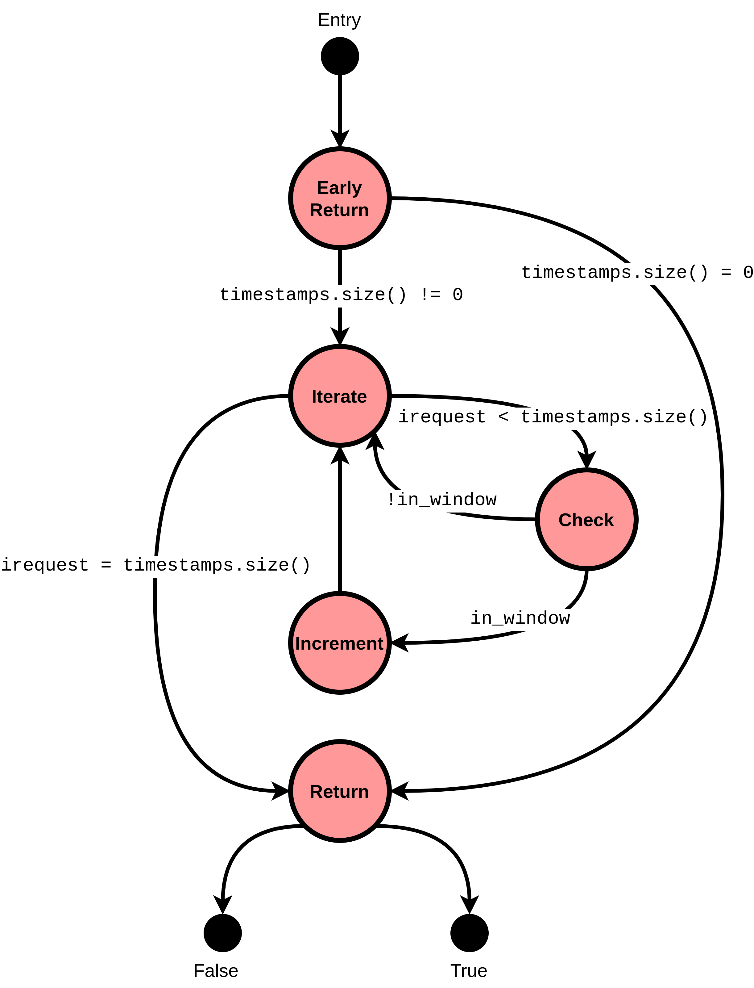
We can split this into an FSM comprising several states:

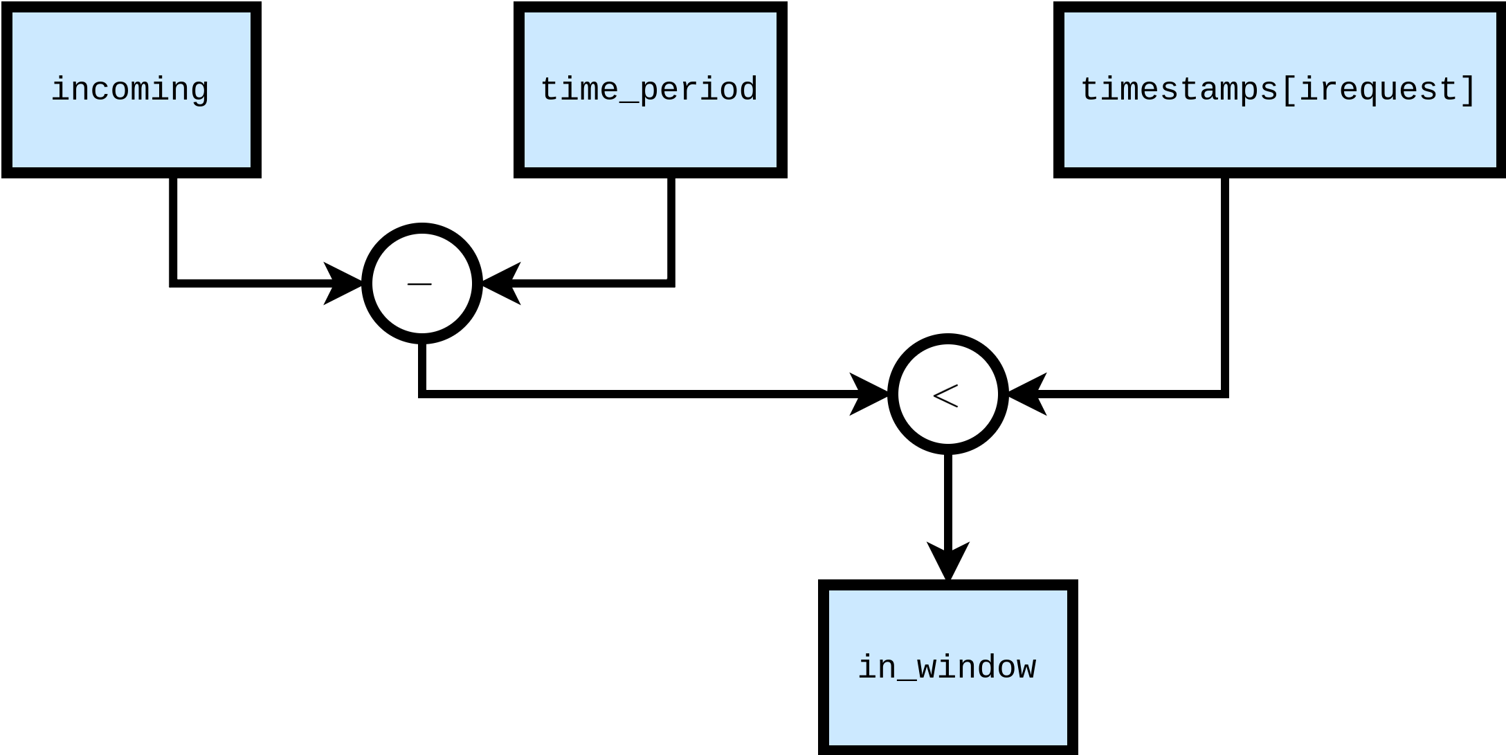
Furthermore, each of the nodes in this FSM comprises purely arithmetic operations; the Check node, for instance, can be drawn as a DFG:

And that's it! We've formulated our algorithm as a graph, upon which we can perform various manipulations and mappings.
Weren't We Supposed To Be Talking About LLVM?
Yes! Although there are plenty of excellent resources out there where you can get a deep-dive on LLVM. Frankly, I'm much too ignorant to have an appreciation for all the facets of LLVM, so any explanation I'd be able to offer would be sub-standard. I'd highly recommend you check out the LLVM project's documentation and tutorials, or for a crash course this blog post is extremely well written.
The bits of LLVM we're interested in, at least for the moment, are the fact that we can render an algorithm into a CFG. In LLVM parlance, each node in the CFG is a "basic block", and each "basic block" comprises a single entry and exit point, within which there is no conditional logic. Hence, a basic block can be realised as a DFG. In order to construct the CFG, LLVM transforms the input language, via its frontend clang, into an "intermediate representation" (IR). For LLVM, the IR form is "single static assignment" (SSA), which happens to be a particularly convenient form in which to perform optimisations (again, go to the resources I've highlighted if you want more information -- I won't pretend to be an expert). For those of you who have seen assembly code before though, it resembles assembly code. Once in SSA form, the LLVM toolchain is able to construct the CFG and constituent basic blocks, and subsequently do a lot of clever optimisation passes (such as removing basic blocks which are unreachable).
For our purposes, we're just after the CFG. We'll then start undertaking various graph analysis treatments to map the CFG into RTL. If we encounter any bits of LLVM or SSA that it's worthwhile explaining, they'll be explained in subsequent posts.
One concept it's worthwhile discussing here is what the final instruction in a basic block looks like; since we're equating a basic block with a DFG, it's legitimate to ask how it forms an edge with another basic block in the CFG. This is where we encounter an issue in equating a basic block to a DFG; technically they are not equivalent. A basic block is a well-defined concept in SSA, while a DFG is more of a model (probably should reiterate that I'm not an expert, or even competent, in this field, so best to take any analogies I make with a large pinch of salt). Each basic block ends with a so-called "terminator instruction". The terminator instruction can take several forms, but the two most common are "return" and "branch" instructions. The return instruction has no successor basic blocks, and instead represents the final point in a function. A branch instruction can be unconditional, in which case it simply represents a single edge to the successor basic block, or conditional, where a predicate is provided and dictates which of two successor basic blocks to branch to.